
We are commonly asked how to wire the Delco SI series alternators upon maintenance or upgrading from an older generator. While this series of unit often runs as a self exciting one wire, agricultural applications also used 3 wire connections to the alternator. If you are looking for the no charge indicator light on the dash to function as well, this should help determine which connection to use.
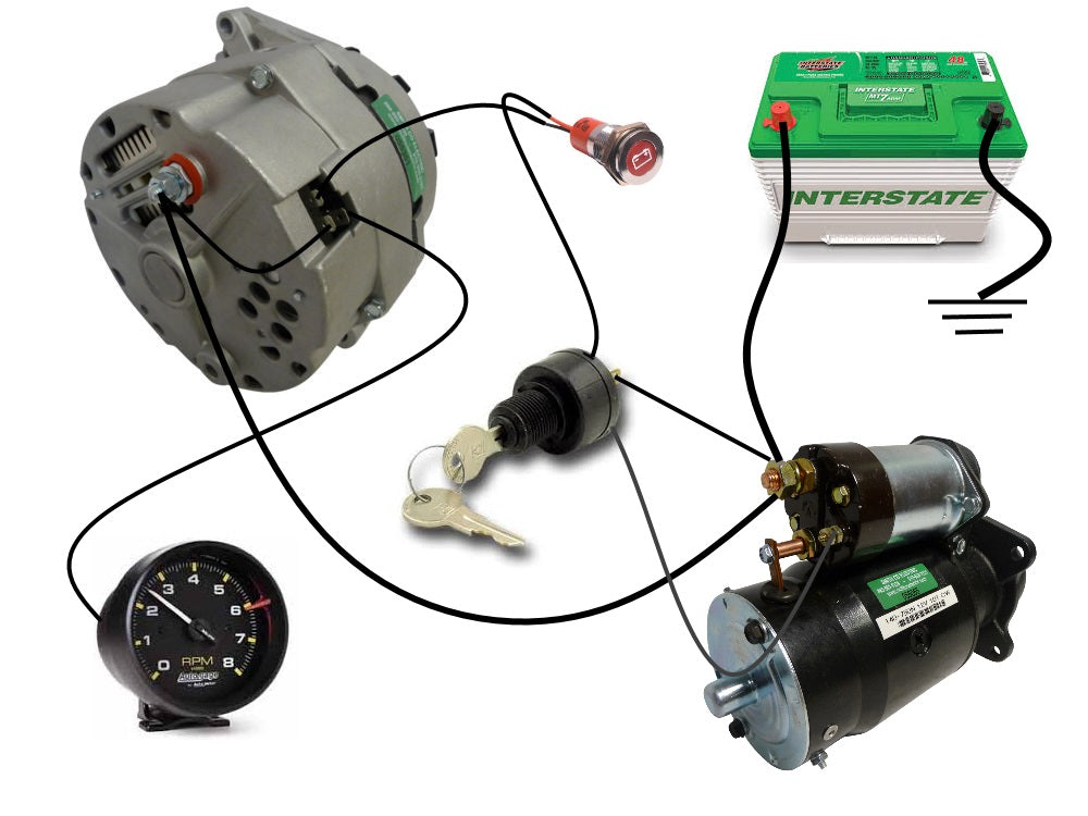
*This diagram shows the simple wiring diagram for negative ground Delco SI series alternators.*
The ignition switch is most commonly powered from the starter battery stud, but source may vary depending on application. With key on power is then transferred through the no charge indicator light to the #1 spade on the alternator regulator connection. This connection acts as a ground allowing the no charge indicator light to work, until the alternator starts charging - the alternator will then push 12v+ back up towards the indicator light cancelling out the circuit and shutting the light off. Depending on switch circuitry there may also be a diode before the #1 spade to prevent the current when charging from back feeding the ignition switch and not allowing unit shut down. *For repair harness including diode see part number 9840-4033*
The #2 spade on the alternators regulator connection may be either powered full time, or may be wired to be on/off with ignition - either will work. For this diagram we are wiring it right back with the alternators output post which is BAT+ full time.
The third spade connection in this diagram is optional and will not be present on all units. This is one of the three phase connections and is most commonly used to function electronic tachometers. This connection is not necessary for unit to function even if it is present.
The main points to remember are both the #1 and #2 regulator connections are BAT+ with key on. The #1 regulator connection must be off with ignition off to prevent battery drain. Alternator ground connection is the casing, grounding back through bracketing and eventually through battery ground cable. Make sure all connections, including battery ground cable, are clean and tight.
*This is a basic wiring guide and will not cover every application or scenario. Always use caution when modifying a system. While Smith Co Electric deems this information accurate, we are not liable for problems arising from use of this information.